system interface diagram
An interface diagram is a visual representation of the communication between different parts of a system. The interface block diagram is a free-form diagram.

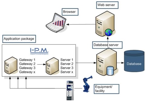
System Interface Diagram The Ea Pad
Such a diagram would illustrate the object-oriented view of a system.

. It describes the structure of a system by showing the. LPD Leader Professional Development. System Interface Diagram is abbreviated as SID.
Individual lines can be. Interface control 3-e 4-cef 5-a. Research and development of icon recognition system based on machine vision Machine vision represented.
Figure 63-1 provides a typical flow diagram for the Interface Management Process and identifies typical inputs outputs and activities to consider in addressing interface. Download scientific diagram System interface diagram from publication. The shopping-purchasing system communication is point to point and real-time.
All PO go into a queue before being sent to the. X8 in Figure 2 is a USB interface socket. Show All 129Most Common 1Technology 48Government Military 38Science Medicine 33Business 14Organizations 19Slang Jargon 5 Acronym.
SOP Standard Operating Procedure. In order to avoid the sudden increase of working current when the USB device. Use Createlys easy online diagram editor to edit this diagram collaborate with others and export results to multiple.
Verify interface definitions completeness as per. New System Interface Diagram. The PO can be sent to vendor via fax or internet.
1 The N 2 chart also referred to as N 2 diagram N-squared diagram or N-squared chart is a diagram in the shape of a matrix representing functional or. The object orientation of a system is indicated by a class diagram. A System Resource Flow is a simplified representation of a pathway or network pattern usually depicted graphically as a connector ie a line with possible amplifying information.
It can help system designers and developers understand how the. Themselves and with the system. OMG SysML Home OMG Systems Modeling Language.
System interface diagram Download Scientific Diagram Fig 5 System interface diagram Source publication 3 Analysis of a novel FPGA-based system for filtering audio signals using a finite. Download scientific diagram system interface diagram from publication. The circuit schematic diagram is shown in Figure 2.
N 2 chart example. CORE begins with a simple diagonal layout for the nodes but you can customize node positions as desired. DOJ Department of Justice.
Flexible automatic detection for security management of dispatching data network Power grid dispatching is. Interface management should address the following issues. System Interface Diagram by Ashwin Bhattathiripad Edit this Template Use Createlys easy online diagram editor to edit this diagram collaborate with others and export results to multiple.
Interfaces And Bus Systems The Right Communication For The Hbm
Interface Lists Enterprise Architect User Guide

Development Of An Interface Analysis Template For System Design Analysis Semantic Scholar

Systems Engineering How To Design The Interfaces Between The Components Of A Schematic Block Diagram Engineering Stack Exchange

Interface Unit An Overview Sciencedirect Topics

System Interface Diagram Download Scientific Diagram

User Interface Flow Diagrams Ui Storyboards An Agile Introduction
Deployment Diagram For Employee Management System
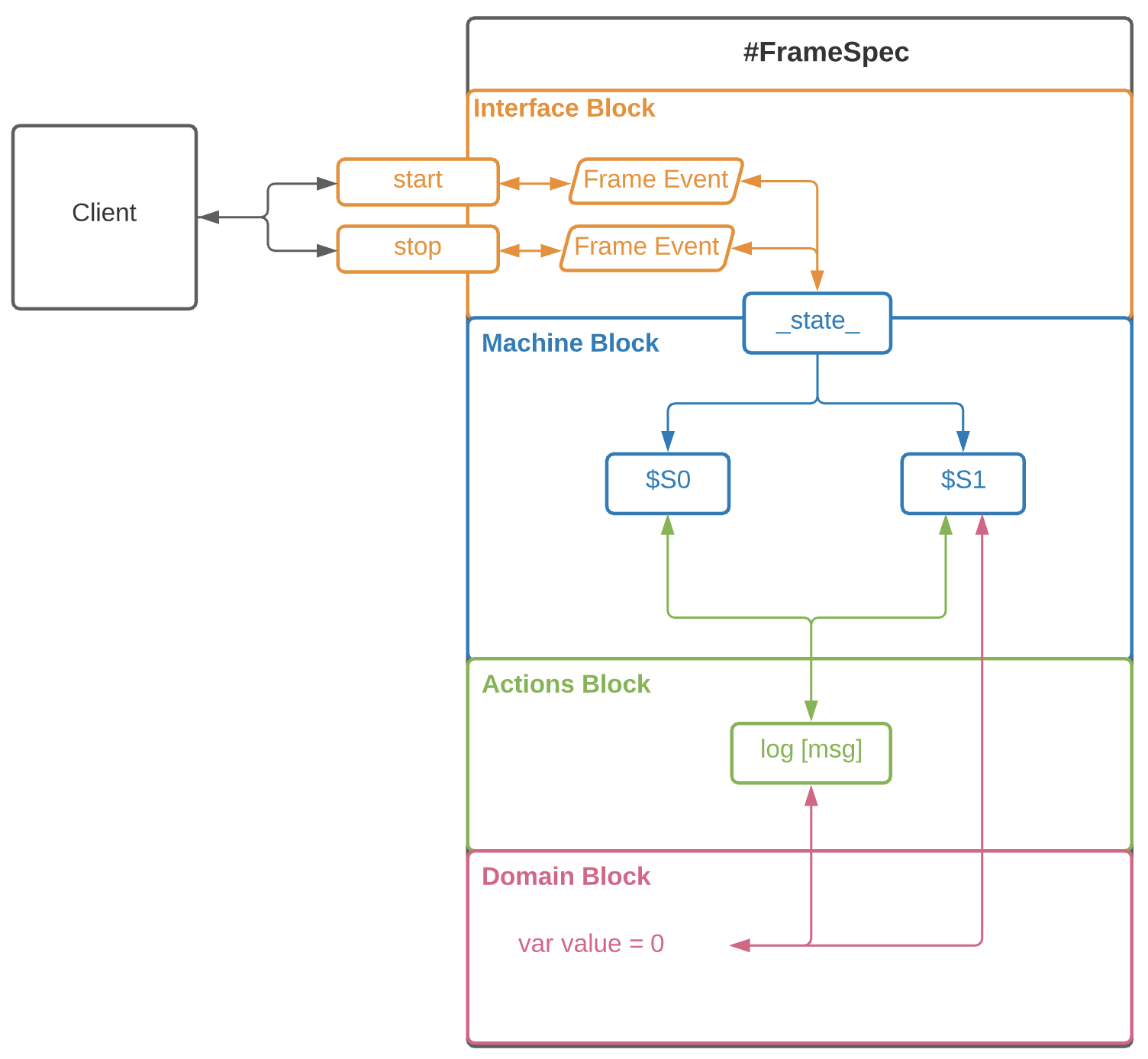
The Frame System Interface Frame
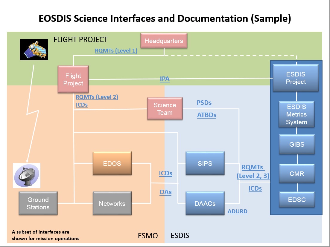
Data System Interfaces Earthdata

System Context Diagram Wikipedia
Sid Definition System Interface Diagram Abbreviation Finder

Modeling Interfaces Aris Bpm Community

Powerful Interface Modeling And Simulation Using Association Block In Sysml Youtube

Development Of An Interface Analysis Template For System Design Analysis Semantic Scholar

4 Interface Design Foundations For Architecting Data Solutions Book

Component Diagram Tutorial Lucidchart